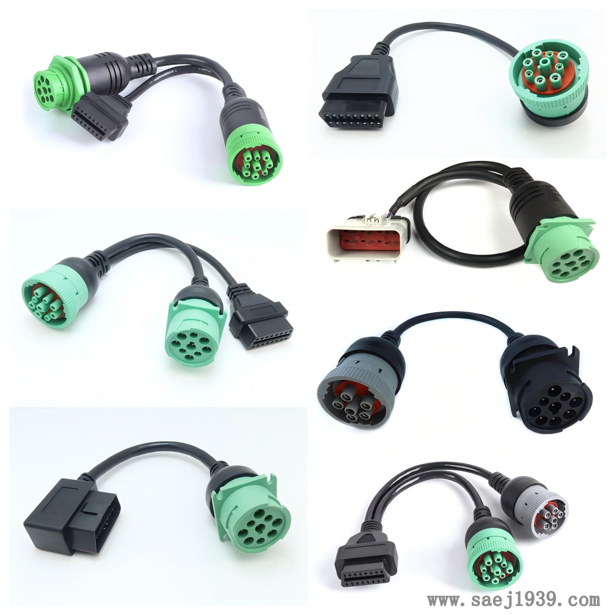
To test the signal transmission quality of J1939 cable using an oscilloscope, the following steps can be followed:

Preparation before testing
1. Choose a suitable oscilloscope
To choose an oscilloscope with sufficient bandwidth, it is generally recommended that the oscilloscope bandwidth be no less than 3-5 times the highest frequency of the signal. For J1939 signals, an oscilloscope with a bandwidth of over 100MHz is usually selected to ensure accurate capture of signal details.
2. Prepare the probe
Connect the oscilloscope and J1939 cable using a suitable probe. The bandwidth of the probe should also match the oscilloscope and have a high input impedance to reduce the impact on the measured signal. Generally, a 10:1 passive probe is selected.
3. Confirm the testing environment
Ensure a stable testing environment and avoid strong electromagnetic interference sources. At the same time, turn off unnecessary electronic devices to prevent them from interfering with the test results.
Connect oscilloscope
1. Connect the probe to the oscilloscope
Connect the signal end of the probe to the channel input interface of the oscilloscope, and connect the ground end to the ground interface of the oscilloscope.
2. Connect the probe to the J1939 cable
Connect the probes of the probe to the CAN-H (high level line) and CAN_L (low level line) of the J1939 cable respectively. If it is necessary to observe differential signals simultaneously, a differential probe or the mathematical operation function of an oscilloscope can be used to subtract two single ended signals to obtain a differential signal.
Set oscilloscope parameters
1. Channel settings
According to the attenuation coefficient of the probe, set the attenuation ratio of the oscilloscope channel. If a 10:1 probe is used, set the channel attenuation to 10X. At the same time, adjust the vertical sensitivity of the channel to ensure that the signal has a suitable display amplitude on the oscilloscope screen. Generally, it can be set to 1V/div first, and then adjusted according to the actual situation.
2. Time base setting
Estimate the signal period based on the baud rate of J1939 signal (usually 250kbps or 500kbps), and then set an appropriate time base. For example, for a 250kbps signal with a period of 4 μ s, the time base can be set to 1 μ s/div -5 μ s/div to clearly observe the waveform details of the signal.
3. Trigger settings
Choose the appropriate trigger source and trigger method. The trigger source usually selects the channel connected to the J1939 signal. The triggering method can choose edge triggering, set appropriate triggering thresholds and triggering slopes (rising edge or falling edge), so that the oscilloscope can stably capture signals.
Test signal quality
1. Observe the signal waveform
The normal J1939 signal has a voltage difference of nearly 0V between CAN_S and CAN_L in idle state. When there is data transmission, there will be significant changes in high and low levels. Observe whether the waveform of the signal is regular, and whether there are any distortions, spikes, overshoots, or undershoots. If there is an abnormality in the waveform, it may indicate a problem with the cable, such as impedance mismatch, electromagnetic interference, etc.
2. Measure signal parameters
Use the measuring function of an oscilloscope to measure parameters such as signal amplitude, period, rise time, and fall time. Compare the measurement results with the standard parameters specified in the J1939 protocol to determine if the signal meets the requirements. For example, the explicit level amplitude of J1939 signal is generally between 1.5V and 3.5V.
3. Detect signal interference
Observe whether there is noise interference in the signal. If there are obvious noise fluctuations on the signal, it may be due to poor cable shielding or the presence of electromagnetic interference sources in the surrounding area. Shielding measures or changing the cable laying position can be attempted to reduce interference.
Record and analyze test results
1. Record test data
Record the signal parameters, waveform images, and other data measured by the oscilloscope for subsequent analysis and comparison.
2. Analyze the test results
Analyze the signal transmission quality of J1939 cable based on test data and observed phenomena. If it is found that the signal quality does not meet the requirements, further investigate the cause of the problem, such as the quality of the cable itself, whether the connection is loose, surrounding environmental interference, etc., and take corresponding solutions.
We chat